CAPCOM NAOMI IO BOARD
 The Capcom Naomi IO-board/converter/adapter allows you to plug a Naomi system into any JAMMA
cabinet. While Sega's own IO boards allow you to do the same, Capcom's converter is the best way
to do it, because:
The Capcom Naomi IO-board/converter/adapter allows you to plug a Naomi system into any JAMMA
cabinet. While Sega's own IO boards allow you to do the same, Capcom's converter is the best way
to do it, because:
- You don't need a separate power supply for your Naomi as the Capcom converter draws voltage from the JAMMA connector
- You don't need a separate audio amplifier for your cabinet. Capcom converter has a built-in amp that outputs the sound to normal JAMMA sound pins. It even has its own volume control knob.
- As far as I know, Capcom converter is the only thing that allows you to play 4 player games such as Power Stone 2 - you can not do that with normal Sega IO boards, even if you have two of them! At least Power Stone 2 ignored input from "Node 2" IO board.
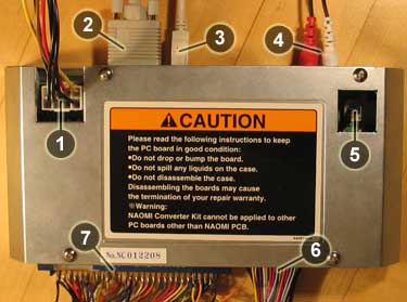
- Power output (supplies power to your Naomi motherboard)
- VGA in (video, standard or high resolution, no medium resolution)
- USB in (for controls)
- RCA in (audio)
- Volume adjustment
- Capcom kick harness (unlike Sega IOs, Capcom IO does not use "unmapped" JAMMA pins for extra buttons, you must use this connector instead. Also, you connect 3P and 4P controls here)
- JAMMA (connect your cabinet here)
EXTRA BUTTONS & 4 PLAYER MODE
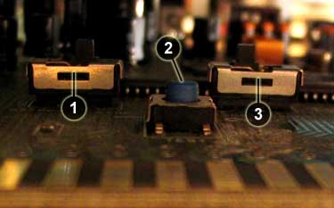 There are two switches and one button located inside the metal case, behind the JAMMA connector:
- Switches between composite and separate H/V syncs. If it is set to "right", composite sync is selected.
- This button works as a Test button. You can of course use the Test and Service buttons on the Naomi itself, which is actually preferred as when you have JAMMA connector connected to the IO, this button can be quite hard to reach.
- This button switches between 2 player and 4 player mode. If it is set to "right", the Capcom IO will act as a normal Sega IO with 2 players and 3 buttons on the JAMMA edge connectors (extra buttons must be connected via Capcom kick harness). If it is set to "left" (like in the picture above), the IO will run in 4 player mode - 2 players via JAMMA plus two additional players whose inputs are connected thru the Capcom kick hareness.
Note, that if you change the position of this switch, you must power off the Naomi system before changes take effect!
PINOUTS FOR BOTH MODES
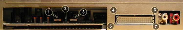
Below you can see a side view of the Capcom IO board. The points of interest here are:
- Mystery? switch
- Test button
- 2 player (right) / 4 player mode (left) selector
- Capcom kick harness pin #33
- Capcom kick harness pin #34
- Capcom kick harness pin #1
- Capcom kick harness pin #2.
|
Function: 1P - GND 1P - Coin 1P - Start 1P - Up 1P - Down 1P - Left 1P - Right 1P - Button 1 1P - Button 2 1P - Button 3 1P - Button 4 2P - GND 2P - Coin 2P - Start 2P - Up 2P - Down 2P - Left 2P - Right 2P - Button 1 2P - Button 2 2P - Button 3 2P - Button 4 |
Pin #: 34 26 24 22 20 18 16 14 12 10 8 33 25 23 21 19 17 15 13 11 9 7 |
|
Function: 1P - GND 1P - Button 4 1P - Button 5 1P - Button 6 2P - GND 2P - Button 4 2P - Button 5 2P - Button 6 |
Pin #: 34 19 17 15 33 21 23 9 |
TESTING THE INPUTS
When wiring the controls, go to the operator menu by pressing the TEST button. Then select "JVS TEST" and from there select "INPUT TEST". On that screen you can test controls, which are shown on the screen in following order:
	   PLAYER x [START][?][UP][DOWN][LEFT][RIGHT][BUTTON#1][BUTTON#2]
	            [BUTTON#3][BUTTON#4][BUTTON#5][BUTTON#6]...
CPS-2/3 KICK HARNESSES
Pinout of CPS-2 and CPS-3 kick harnesses are the same as the 4 player Naomi Capcom IO! Simply plug in and play!